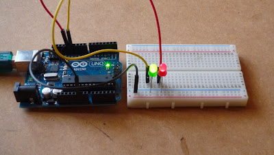
Hardware setup.
The hardware setup was straightforward and just needed another LED and an extra jumper wire. How I connected it al together.
 |
| Red lit. |
 |
| Green lit. |
- From digital pins 12 & 13 to LEDs +ve pins.
- LEDs -ve pins connected to ground rail.
- Ground rail connected to power ground pin.
- Done.
Software.
I built the sketch from scratch using the principals learnt in lesson 1.
// Example 01 Mod : Blinking LEDs : James Margarson 30/09/13 :
const int LED = 13;
const int LED0 = 12;// LEDs connected to
// digital pins 12 & 13
void setup()
{
pinMode(LED, OUTPUT);
pinMode(LED0, OUTPUT);// sets the digital
// pins as outputs
}
void loop()
{
digitalWrite(LED, HIGH); // turns LED on
digitalWrite(LED0, LOW); // Turns LED0 off
delay(250); // waits for 250 milliseconds
digitalWrite(LED, LOW); // turns LED of
digitalWrite(LED0, HIGH);// turns LED0 on
delay(250); // waits for 250 milliseconds
}
From the original example sketch I added a few extra lines of code highlighted to show my additions to control the flashing of the two LEDs.
The final result.
No comments:
Post a Comment